Nuclear grade graphite gasket
General Features
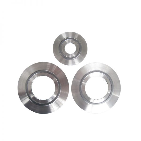
Nuclear grade graphite gasket consists of three parts: outer ring, seal ring and inner ring. When the gasket is working, the flange metal surface is always in contact with the gasket limiting ring, and the sealing stress is kept constant during sealing service. The deformation of the flange is reduced, and the sensitivity of the sealed coupling part to external bending moment, temperature and pressure changes is ensured. The sealing system is continuously safe, effective and reliable. Applicable to boron-containing water, cooling water, steam, demineralized water, oil, air, nitrogen, oxygen, 30% sodium hydroxide solution, 7% nitric acid solution and other media.
Description
Product Specifications
Nominal diameter: 1/2′′~28
Technical Parameters
| Test item | Unit | Value |
| Compensation rate | % | 18~27 |
| Rebound rate | % | ≥20 |
| stress relaxation rate | % | ≤10 |
| Seal Leakage Rate | Pa.m3/s(helium gas) | ≤1.0×10⁻⁶ |
Applications
Working temperature: -200°C~600°C
Working pressure: ≤50MPa
Usage
Applicable to nuclear power supply system 1,2,3 safety level process, instrumentation line flange, body seal, and vaporizer primary and secondary sides and regulator manhole or hand hole seal.
Gasket Structure
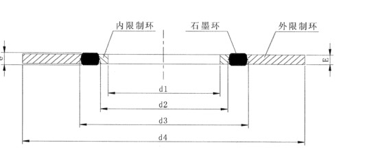
The graphite gasket consists of a metal inner ring, a graphite ring, and a metal outer ring. The middle of the gasket is a high-purity expanded graphite ring.
Structure Diagram

Gasket Size
The graphite gaskets for flange seals match the flange sizes of ASME B16.5 and ASME B16.36. For non-standard flanges and the implementation of other standard flanges, the gaskets also determine the gasket size according to the flange requirements.
The gasket size d1 is matched with the inner hole of the flange. Between d2 and d3 is the effective sealing surface of the gasket. d4 should be smaller than the diameter of the center circle of the flange bolt hole minus the diameter of the bolt hole.
| DN | d1 | d2 | d3 | e | E | d4 | |||||
|---|---|---|---|---|---|---|---|---|---|---|---|
| CL 150 | CL 300 | CL 600 | CL 900 | CL 1500 | CL 2500 | ||||||
| 15 | 17 (15) | 23 | 31 | 4.4 | 3.2 | 46 | 52 | 52 | 62 | 62 | 69 |
| 20 | 23.7 (21) | 30 | 38 | 4.4 | 3.2 | 56 | 66 | 66 | 69 | 69 | 75 |
| 25 | 29.7 (27) | 36 | 48 | 4.4 | 3.2 | 66 | 73 | 73 | 78 | 78 | 84 |
| 40 | 50.7 (42) | 57 | 69 | 4.4 | 3.2 | 84 | 94 | 94 | 97 | 97 | 116 |
| 50 | 65.7 (56) | 72 | 84 | 4.4 | 3.2 | 100 | 107 | 107 | 139 | 139 | 141 |
| 65 | 76.7 (67) | 83 | 95 | 4.4 | 3.2 | 119 | 127 | 127 | 160 | 160 | 163 |
| 80 | 90 (83) | 99 | 115 | 4.4 | 3.2 | 132 | 146 | 146 | 166 | 170 | 192 |
| 100 | 110 (99) | 119 | 135 | 4.4 | 3.2 | 170 | 178 | 190 | 203 | 205 | 231 |
| 125 | 140 (8.210.33.29) | 149 | 165 | 4.4 | 3.2 | 194 | 213 | 237 | 244 | 250 | 276 |
| 150 | 161 | 174 | 194 | 4.4 | 3.2 | 219 | 248 | 262 | 285 | 280 | 312 |
| 200 | 212 (205) | 225 | 245 | 4.4 | 3.2 | 276 | 304 | 316 | 354 | 348 | 382 |
| 250 | 265 | 285 | 305 | 6.6 | 5 | 336 | 357 | 396 | 431 | 430 | 471 |
| 300 | 318 (308) | 338 | 358 | 6.6 | 5 | 406 | 418 | 453 | 494 | 515 | 543 |
| 350 | 350 | 380 | 402 | 6.6 | 5 | 446 | 481 | 490 | 517 | 575 | |
| 400 | 407 | 431 | 461 (456) | 6.6 | 5 | 510 | 535 | 561 | 571 | 637 | |
| 450 | 454 | 484 | 514 | 10 | 8 | 545 | 592 | 609 | 634 | 698 | |
| 500 | 508 (500) | 538 | 576 | 10 | 8 | 602 | 650 | 679 | 695 | 752 | |
| 600 | 610 (606) | 642 | 682 | 10 | 8 | 713 | 771 | 786 | 833 | 896 | |
The values in brackets are 1500 lbs and 2500 lbs.
Dimensional Deviation
Diameter limit deviation (unit: mm)
| Nominal diameter DN (mm) | Graphite Ring | Inner and Outer Rings | ||
| D2 | D3 | D1 | D4 | |
| ≤200 | ±0.3 | ±0.3 | +0.5 0 | 0 -0.8 |
| 250-600 | ±0.5 | ±0.5 | +0.8 0 | 0 -1.3 |
Thickness limit deviation (unit: mm)
| Graphite Ring | Limit deviation | |||
|---|---|---|---|---|
| Thickness(T) | Limit deviation | DN | Inner Ring | Outer ring |
| 4.0-5.0 | ±0.22 | ≤200 | +0 -0.10 | +0.10 -0.05 |
| 6.0 to 10.0 | ±0.22 | 200<DN≤600 | +0 -0.15 | +0.15 -0.10 |
Metal ring flatness: 0.1mm (DN≤200); 0.2mm (200<DN≤600)
Appearance quality
No defects, such as scratches, voids, irregularities, and rust spots, which affect the sealing performance, are allowed on the upper and lower surfaces of the graphite ring of the gasket.
The surface of the inner ring and the outer ring shall have no defects such as burrs, uneven or rusty spots; the distances between the upper and lower sealing surfaces of the graphite ring of the gasket and the upper and lower surfaces of the ring shall be equal; the graphite ring shall be fixed between the inner ring and the outer ring; Allow loosening.
Gasket Advantage
| Items | Graphite Gaskets |
|---|---|
| Principles of sealing | Metal-touch-metal design concept, the gasket stress is kept constant during the sealing service period, so as to ensure the continuous and effective sealing process. |
| Sensitivity of thermal shock and pressure fluctuations | Constantly maintain gasket pressure during initial design |
| Anti-fatigue failure | The pure graphite ring is assembled between two metal rings, the limit ring is subjected to normal stress, and the stress value is far less than the elastic limit of the material, so no fatigue failure occurs. |
| Overall stiffness | Using metal-impact-metal design, the overall stiffness of flanges and gaskets has been greatly enhanced |
| Installation requirements | Metal-touch-metal design allows overloading |
| Effects on Spouse Flanges | Long-term use without damage to the flange surface |


